Long before university, I began learning music production. One of the most important skills in music production is to know how to use an equalizer. In an equalizer, one can choose the type of filter (high-pass, low-pass, band-pass, etc.) and set the Q-factor. When I later learned how to design filter circuits, I wanted to create one. I decided to design a two-way speaker system with a woofer and a tweeter. The woofer would be fed the low-passed audio signal while the tweeter would be fed the high-passed audio signal.

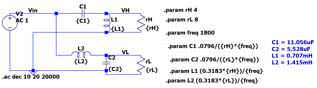
I referenced this article to help me design the filter. I chose to design a 2nd-order filter instead of a 1st-order filter because it provided a steeper roll-off rate. As seen above, both LP and HP filters are RLC circuits.
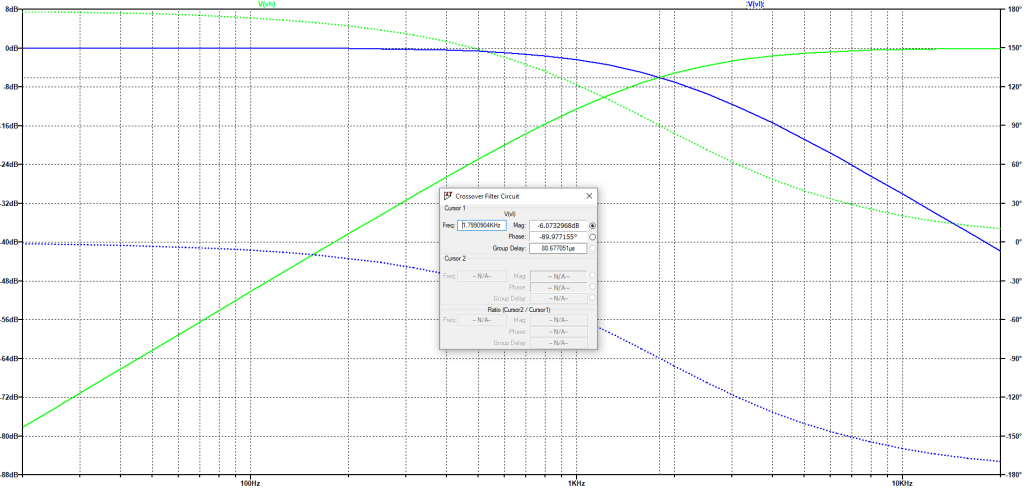
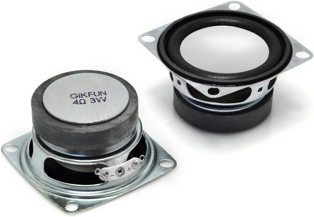
After verifying the filter in LTspice, I went ahead and ordered the parts. For the drivers, I purchased a 6.5″ woofer and used a 2″ tweeter that I had lying around from a kit.

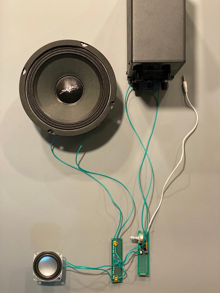
After assembling the circuit. I could clearly hear the effect that the LP and HP filters had on each driver output (I had listened to the individual drivers before any filtering). The woofer produced the bassy notes and a decent portion of the mids while the tweeter produced the clarity and sibilance.
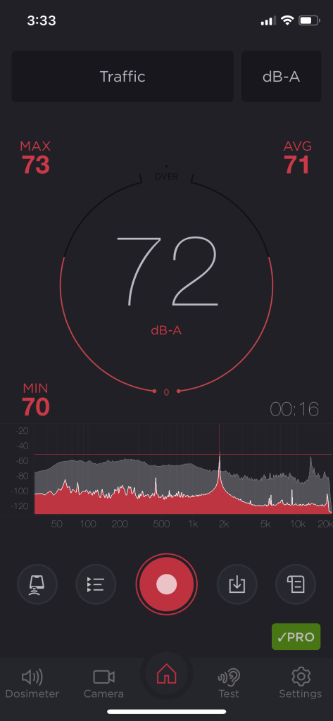
The one issue with the setup was that the drivers were fairly quiet. A test tone of 1.8kHz (the crossover frequency) was inputted so that both the woofer and tweeter provided an equal magnitude response. At max volume and with my phone spaced 15 inches away, an output magnitude of 72 dB-A was reached, equivalent to the loudness of traffic.
At this point, I made the decision to add an audio amplifier. I had initially tested some transistor-based Class-A amplifiers using multiple stages of the common emitter and common collector amplifier. However, the circuit became more fiddly as I went on and I knew that I would have to run some more LTspice simulations before building a multi-stage amplifier.
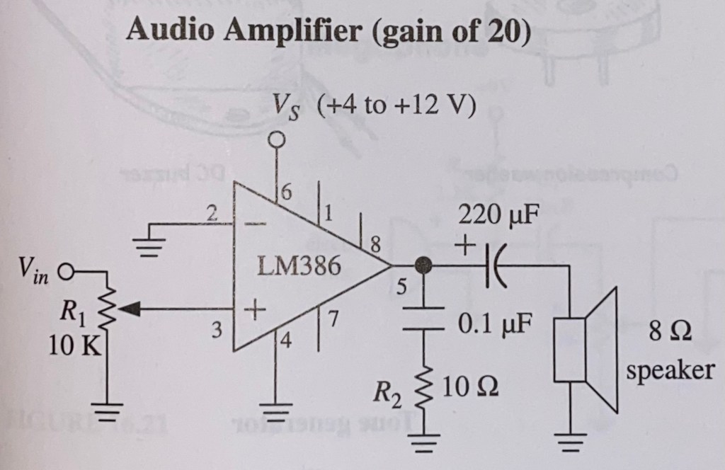
Instead, I opted to use an LM386 as an audio amplifier which was convenient since I already owned one. I referenced this schematic from a textbook to build my circuit.
After the building the circuit, I connected the input of the crossover filter to the output of the audio amplifier, connected the power rails to a power supply, and began playing audio. It was quickly apparent that the audio amplifier was much louder than before, however with an enormous amount of noise. Touching the potentiometer also made the distortion worse.

Looking for solutions online, I found some articles which suggested placing capacitors to filter out the noise. I first added a capacitor between the bypass (pin 7) and GND which slightly reduced the noise. The biggest improvement was a result of placing a capacitor between the + and – power rails (6 and 4) to smooth the supply voltage. Afterwards, the noise was effectively eliminated and touching the potentiometer no longer caused noise artifacts.
Once I was done with my audio amplifier, I measured the new loudness with my phone spaced 15 inches away (same as before).
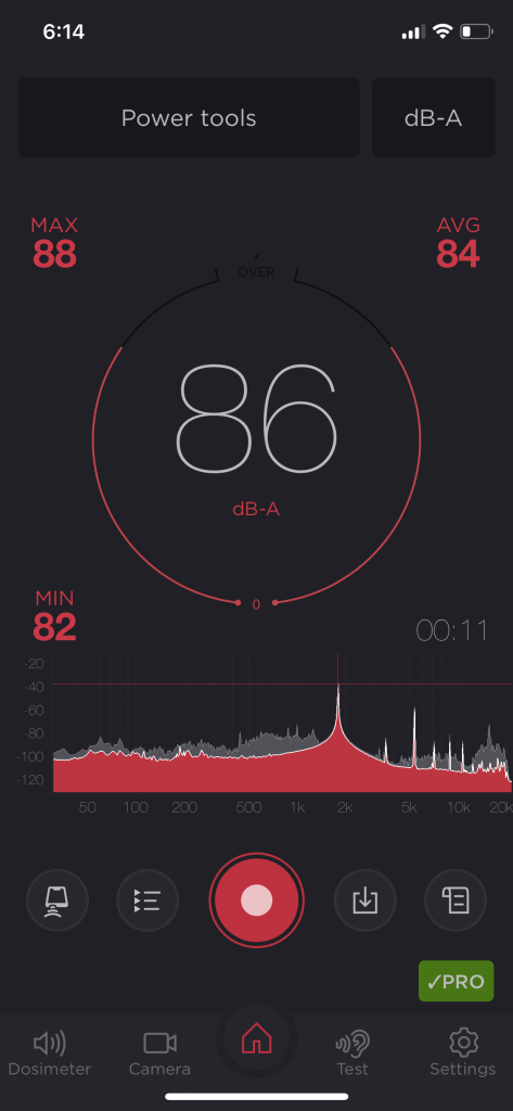
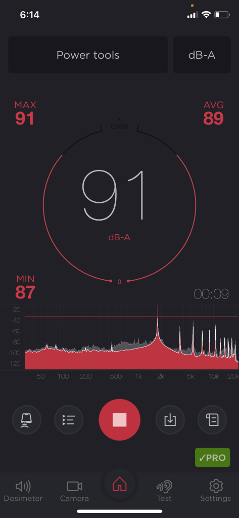
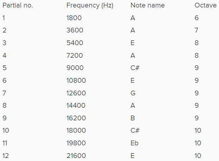
The audio amplifier increased the usable audio output by 14dB-A and up to 19dB-A when turned to the max volume. I suspect the audio amplifier is saturating at this volume because the frequency response graph shows a number of upper harmonics above the 1.8kHz fundamental tone. The frequencies of the peaks strongly correlate with this harmonic series calculator.
I enjoyed making this audio amplifier for its connection to my background in music production. I would not mind revisiting this project, perhaps using a better IC and a more complex circuit to improve the quality and amplification of the audio.
