I worked on this project in conjunction with two other teammates, centering around hardware integration and programming a simulated car ECU on the second Nucleo board.
The OBD2 port reader is able to send and receive classic CAN PIDs through the car’s CAN bus. It can then translate the received data into real-world values. It will present RPM, Speed, and coolant temperature on the LCD. It can also display the current rpm on a display composed of six LEDs, along with an added LED to indicate when to shift to the next gear. All additional data from CAN will be displayed on a virtual terminal through LPUART. The system is fully operational.
The main.c file primarily deals with LCD printing, hex PID math, and calling the “request” and “receive” functions from CAN1.c. The infinite while loop constantly cycles through and sends out an array of PID requests. Then it checks the messages received and will only read the data if the message is a single frame, coming from a desired ECU, and containing a return tag (0x41). It will then match the PID to its corresponding function and manipulate the raw data into data that can be displayed and stores it as a variable. After this, the data is displayed on LPUART, the LCD, & LEDs. CAN1.c is the bulk of our code. It first initializes the CAN bit rate, registers, and peripherals. The initialization function will set the CAN clock to 80MHz, make the initialization request flag high, enable automatic bus management, configure the bit timing register and filter master register, and then exit initialization mode. The BTR is important for timing as it includes synchronization bits and buffers. The BTR has sampling occur at 11 + 1 = 12/16 time quanta or 75% through the bit. This was a very subtle detail learned during the initialization process. This was done since it is recommended to sample at 75-90% of a CAN bit for stability purposes. The steps on how the send and receive functions work are listed below:
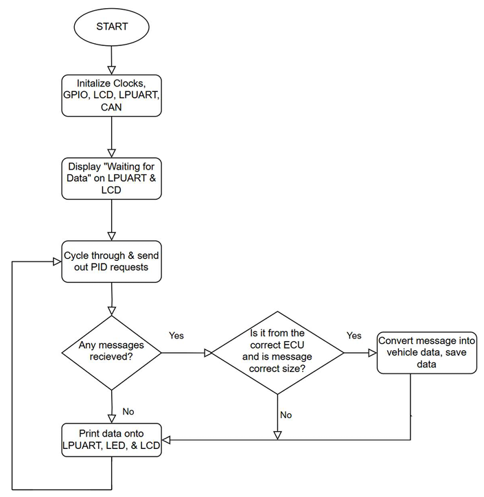
General recipe for sending/receiving
• Wait for the controller’s “message pending” (or empty mailbox if you are sending a frame) flag
• Read or specify the header word: identifier, frame type, and length
• Load in the high and low data bytes (4 each)
• Tell the controller you’re done with the slot so it can queue the next frame

Schematic of OBD2 Port Reader, when reading CAN data from car
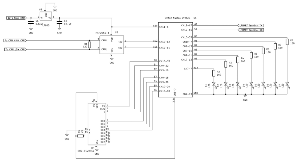
Schematic of OBD2 Port Reader when reading CAN data from another Nucleo
