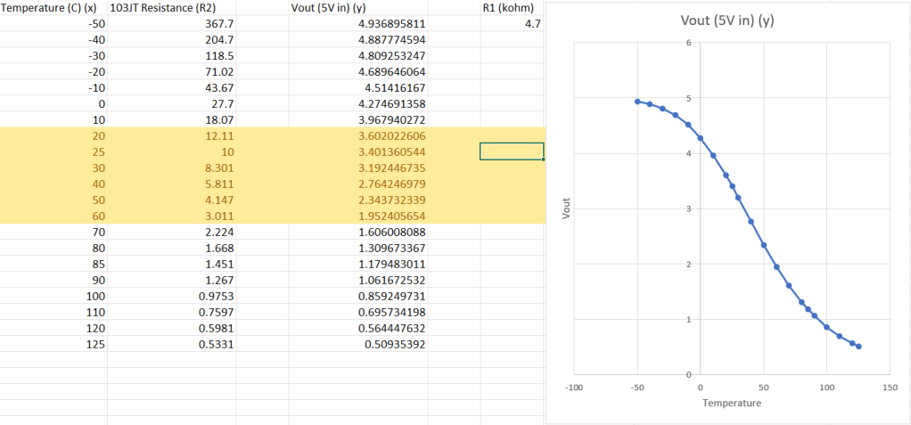
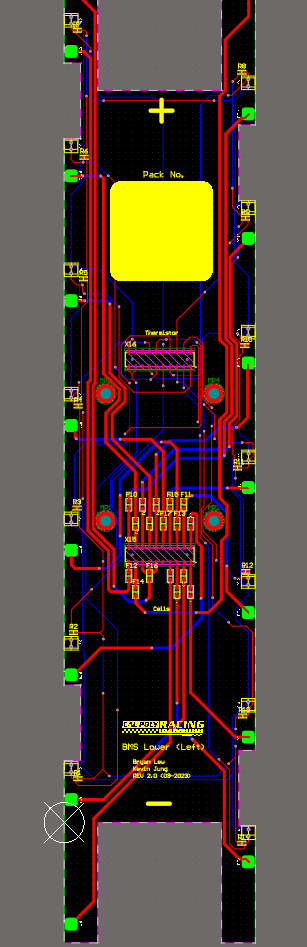
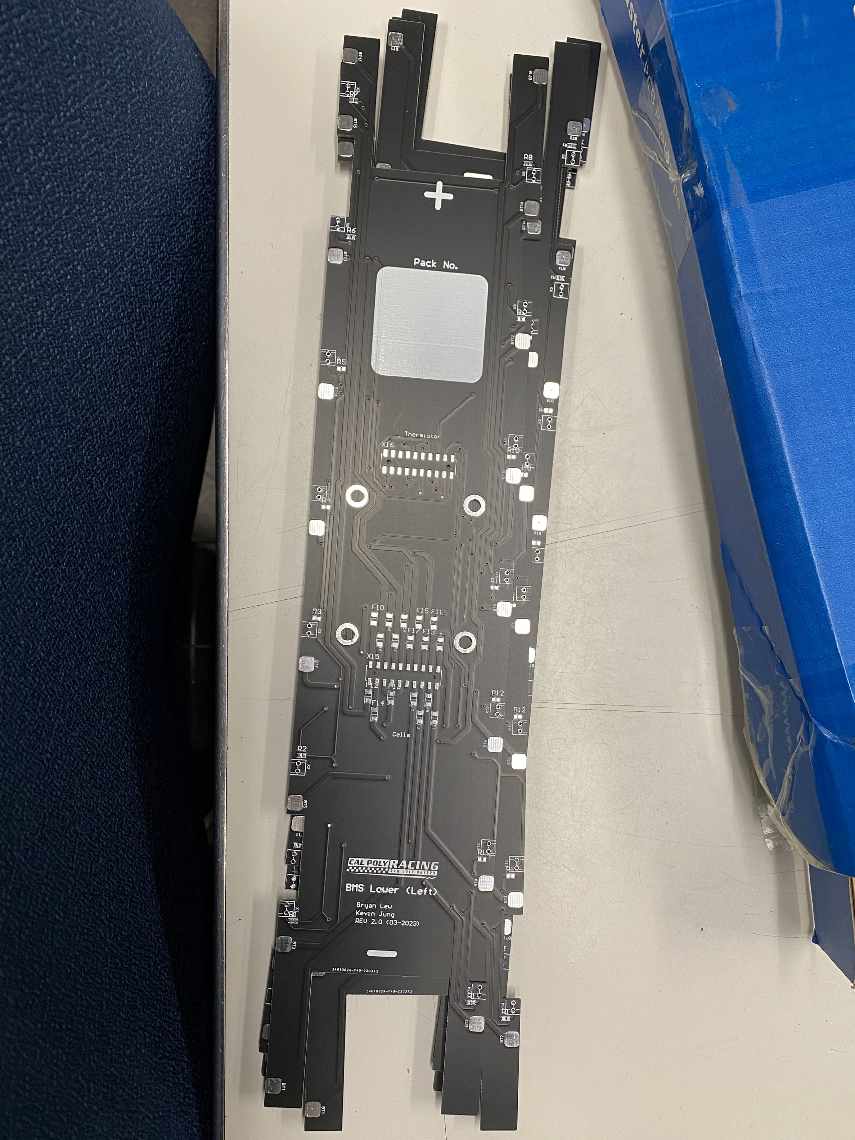
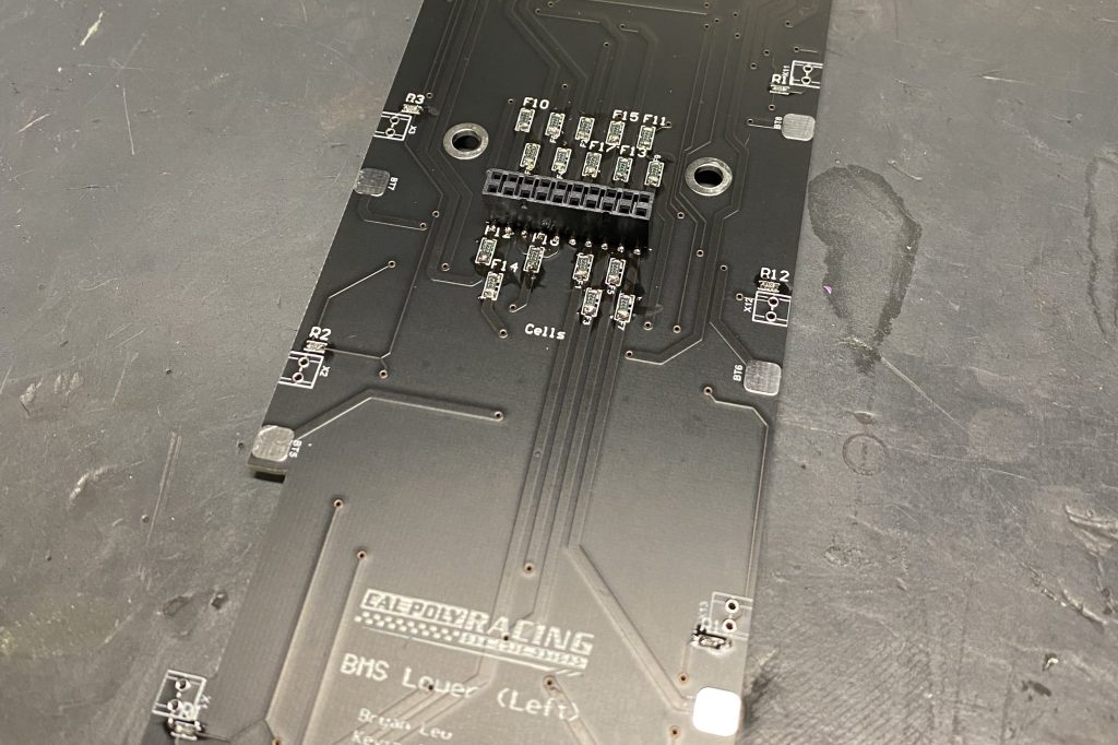
The year before I became HV-Electronics Lead, I designed the schematic, layout, and helped manufacture the board which measured 16 voltage nodes and temperatures of the 23′ battery modules, each trace containing overcurrent protection. The temperature was determined using a thermistor and a voltage divider circuit. The R1 resistance was tuned to produce a linear Vout in the optimal temperature range, 20° C to 60° C. A linear Vout makes for easier, linear mapping of output voltage to temperature.