This was my main project for a decent chunk of my summer. After taking a energy conversion electromagnetics class and dealing with power electronics in FSAE, I decided to take on the challenge of making a permanent magnet synchronous machine.
After researching and trying different design software such as QuickField and FEMM, I settled on MotorAnalysisPM, a program dedicated to the design of permanent magnet machines. The major reasons behind the decision were its free price and relative simplicity in workflow compared to other free legacy software.

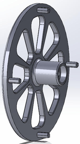
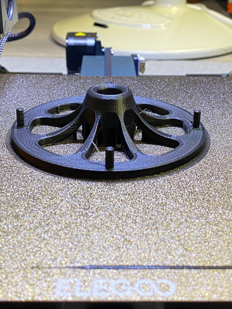
I began designing the rotor which some back and forth to get to a point that I thought was sufficient enough. The picture above is the final rotor design after trying multiple simulations with different magnets and rotor sizes. I was also simultaneously drawing the rotor in Solidworks, a program which I had never used before to design anything substantial.

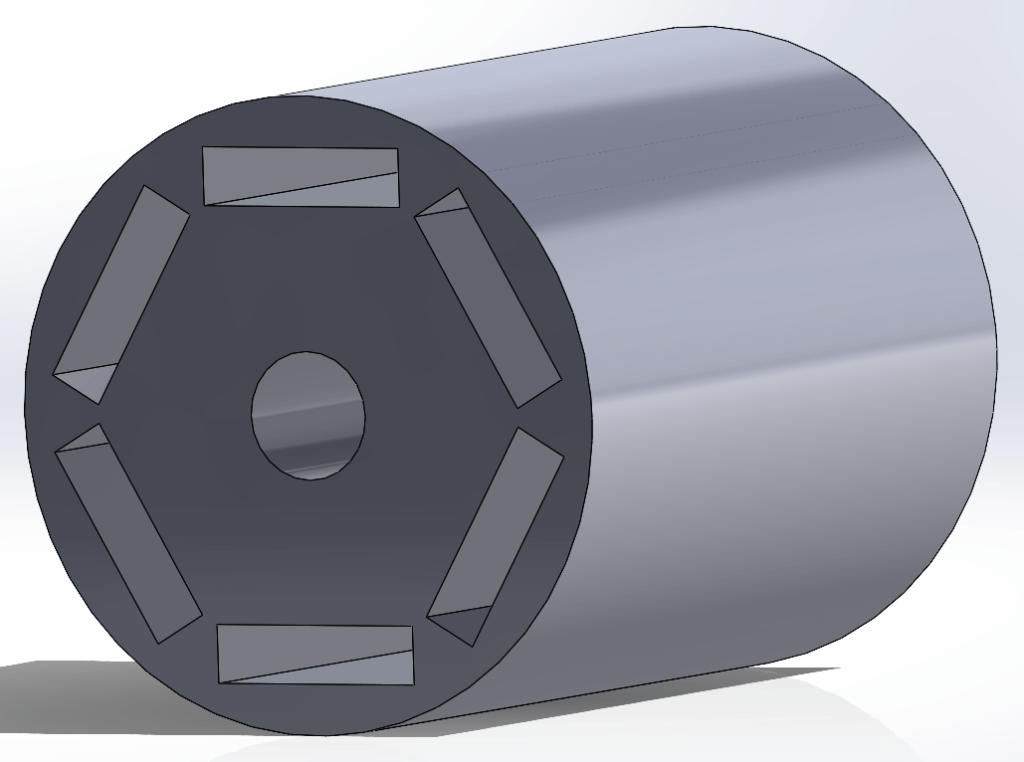
The rotor was the first part I designed in Solidworks. Towards the end of the project, the shapes of the parts became more complex as I learned how to use the program.
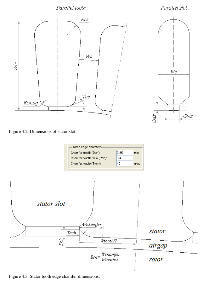
These are the dimensions that MotorAnalysisPM allows you to alter if you decide to use the built-in stator generator. I did make some custom stator DXFs but reverted to the one in the designer since it was the same, if not better geometry than the ones I created, plus it was easier to change on the fly.
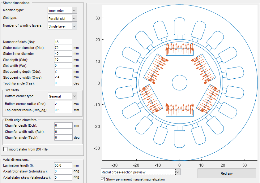
The parameters I chose are on the left-hand side. I added fillets to reduce points of stress and estimated the size of the openings, something which would prove a nusance later. I chose an 18 slot design balance creating a smoother RMF (rotating magnetic field) with a larger slot for simplicity and ease of winding installation. The outer diameter of the stator was driven by the amount of Iron PLA filament I had. I calculated the overall volume of the stator and rotor to determine filament usage. I also chose a single winding layer for the same philosophy of easier winding installation given the size constraints.


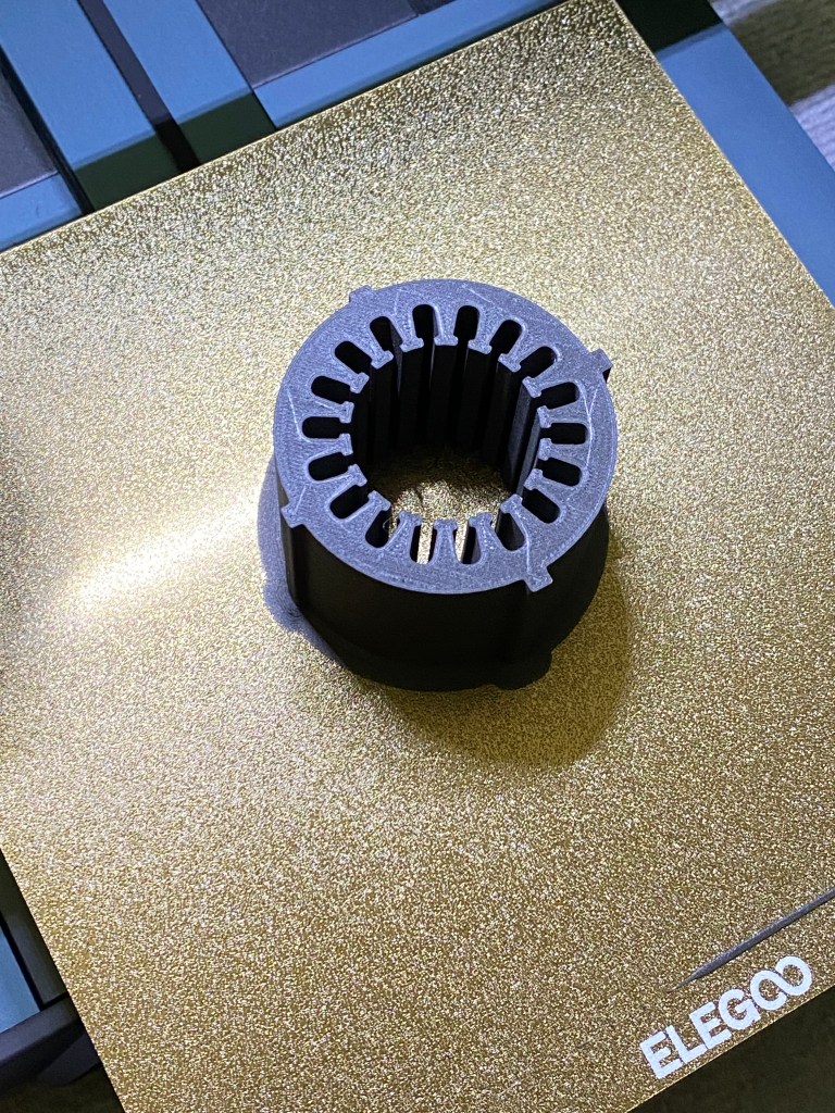
I recreated the exact stator from MotorAnalysisPM in Solidworks and this is what came out.
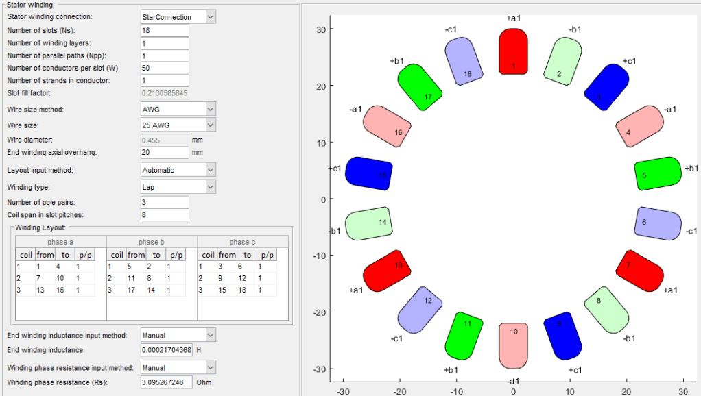
Most of the settings here are auto-generated so I mostly kept them the same. I changed the wire size to the 25AWG motor wire that I would be using.
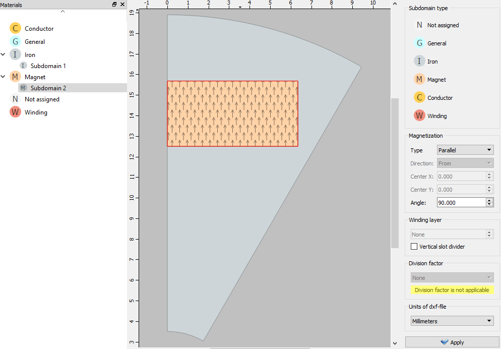
Next, I had to fill out the materials editor which involved some extra work due to my use of Iron PLA instead of regular iron. I used Iron PLA for a number of reasons which include the high cost of outsourcing my design to a CNC company, I would need to laminate (split into many thin discs) the rotor and stator to reduce the generation of eddy currents due to iron’s conductivity, I would have to find a way to electrically insulate each lamination to prevent conduction, and it would give me an excuse to use my 3D-printer. With Iron PLA, I do not have to worry about laminations since the majority of the material is non-conductive plastic, just infused with iron flakes. Measuring with a multimeter, it does not conduct.

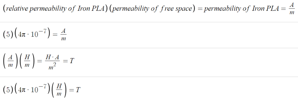
Fortunately, the datasheet for the Iron PLA includes the permeability and point of magnetic saturation. I decided to use the material’s relative permeability instead of permeability and multiplied by the permeability of free space. The resulting value is the same as the permeability value listed in the datasheet so either way works. I used the lower relative permeability value since I had the version of Iron PLA with a lower percentage of iron. The provided point of magnetic saturation (0.15T) is where the B-H curve flattens out, or saturates.
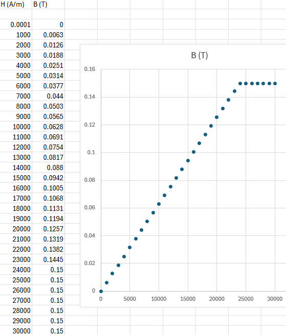
I plotted the derived formula into Excel which resulted in this B-H “curve”. B-H curves normally contain a linear region in the middle where this formula can be used. The non-linear regions near 0 and saturation were disregarded for simplicity.
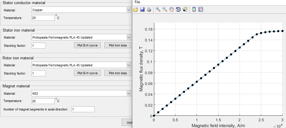
These values were then imported into MotorAnalysisPM.

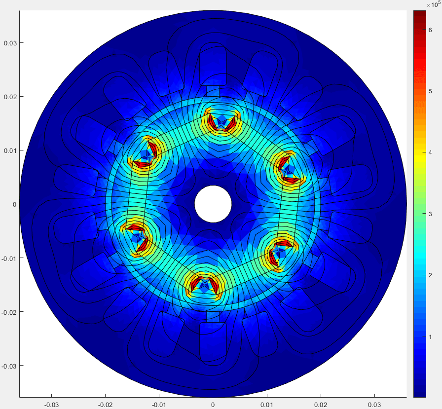
Above is the auto-generated mesh that is used for the simulations.

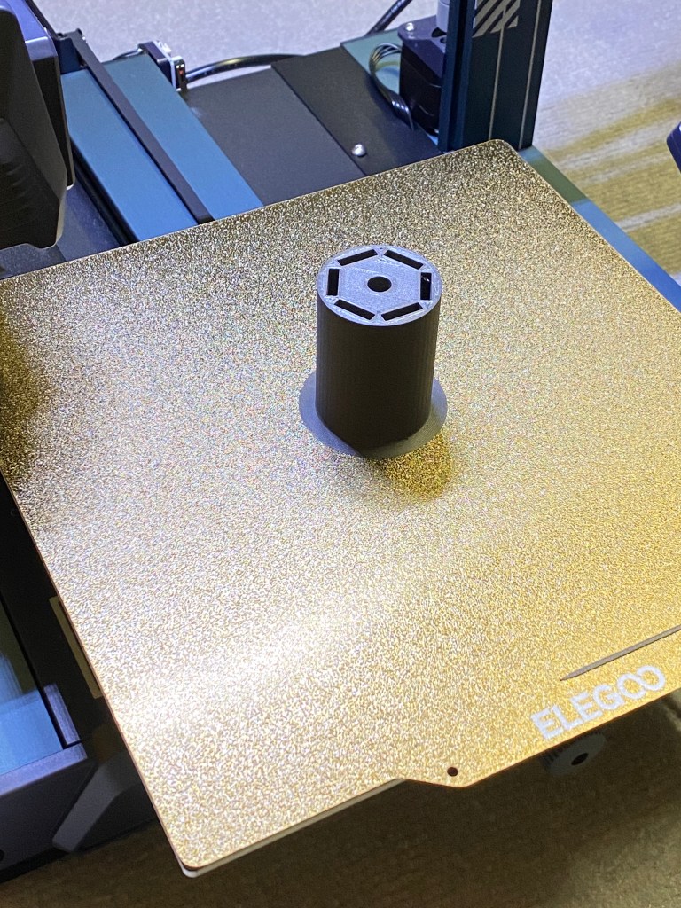
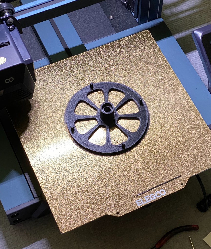
At this point, it was time to start printing the assembly.

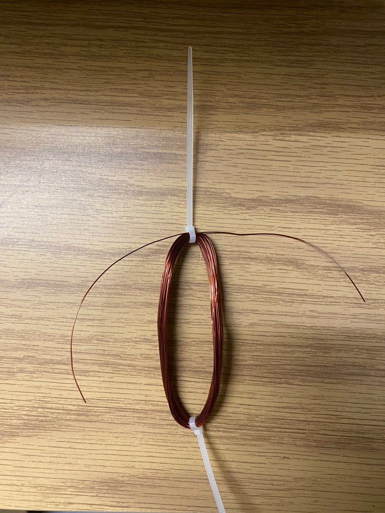

I began my attempt at inserting the windings into the stator at which point I realized the 150 turn windings were not going to fit. I wanted to remake the stator but for the time being, I reduced the windings to 50 turns. One thing to note is that the winding locations are incorrect in the picture above but are fixed by the time I started testing it.
Whilst this was occuring, I began designing the outer casing.


The Front Cap was the last part I made in Solidworks. I added a large countour which extended the usable length of the motor shaft.
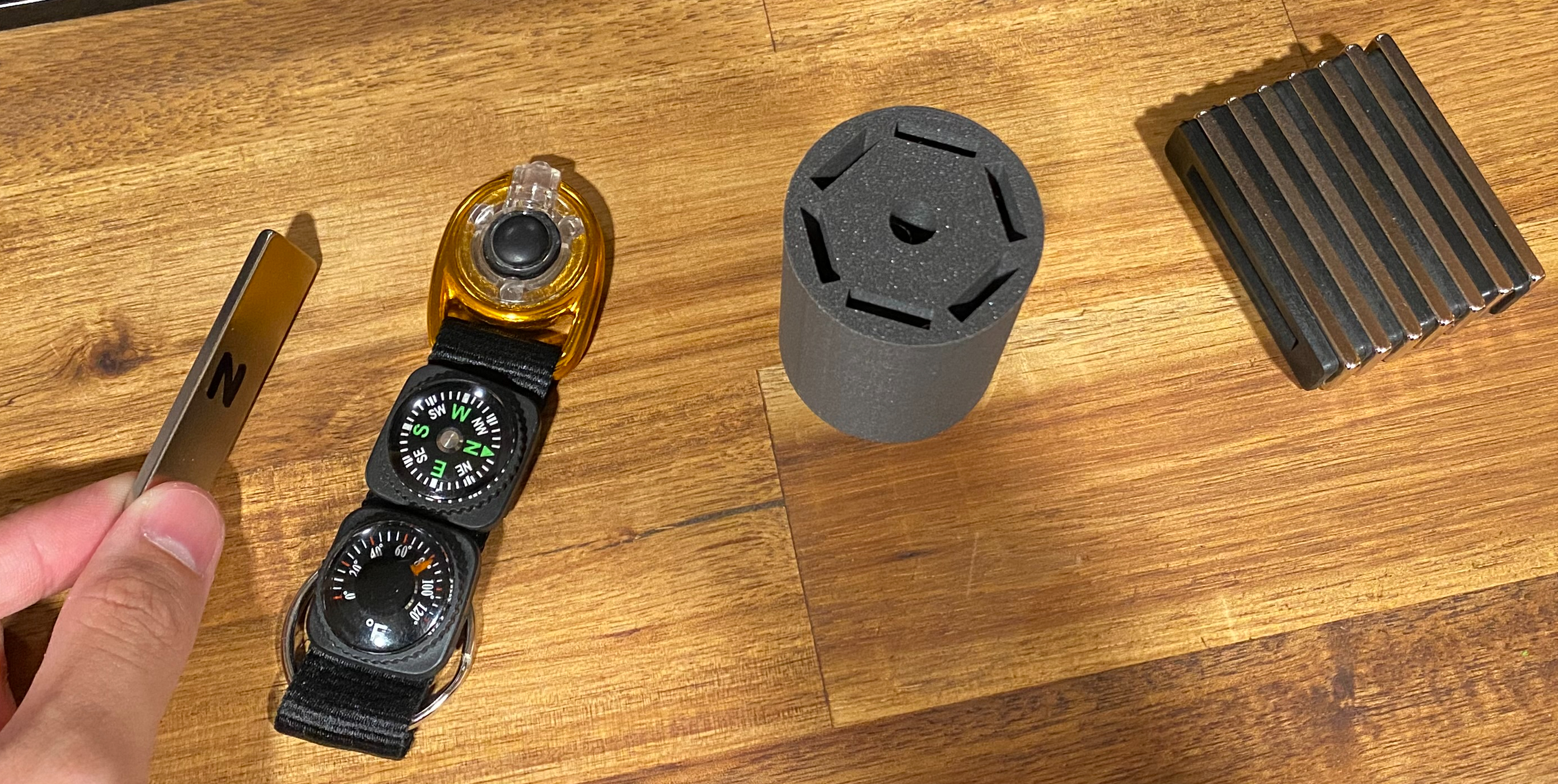
After printing all of the parts, I inserted a stainless steel shaft into the rotor and added bearings to each of the caps before assembling everything.
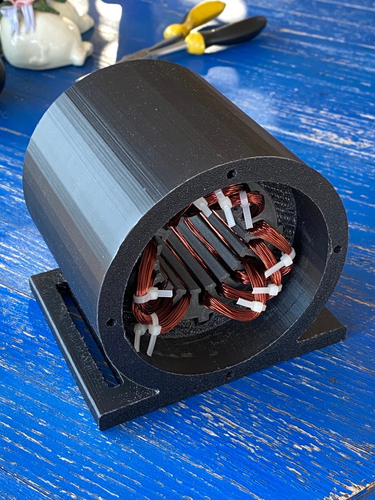

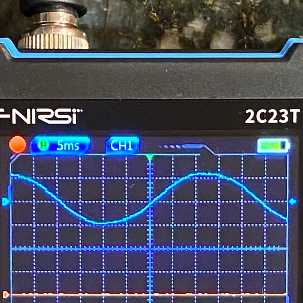
This was the first time in the project that I tested the assembly. I spun the shaft with a drill and a sine wave appeared on my oscilloscope which was a good sign.
Next, I attached an LED to see if this generator could power it.

The LED was being powered but it could be improved. I quickly threw together a simple three-phase rectifier which would allow me to utilize all three phases, remove the AC off half-cycle, and provide a constant DC voltage for the LED.
The LED became a lot brighter. Still, for a drill speed of 2380rpm, the power being generated was admittedly not a lot. A major part of this is attributed to the reduction of each winding from 150 turns to 50 turns because of the size of the stator slot and the subsequent difficulty to insert each winding. Another factor is the low reluctance of the Iron PLA compared to regular iron.
Up until this point, I had been using the machine as a synchronous generator. I wanted to try using it as a three-phase synchronous motor but had been holding off since I had no access to a three-phase source.
I initially tested the motor using a DC power supply connected to one of the phases relative to neutral. The first sign was promising since the rotor lined up with the powered phase’s windings.
Afterwards, I obtained access to a variable frequency drive which would allow me to power all three phases and control the frequency of the motor.

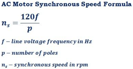
I marked one side of the motor shaft with a sharpie so that I could visually count each cycle. I ran the motor at a frequncy of 3 Hz and recorded a one minute video. Afterwards, I counted the total number of cycles which resulted in an rpm of 60, matching the formula above.
An issue that I ran into was that above 4.5Hz, the VFD would go into an error mode and display an error code related to overload/short-circuit protection. I was never able to resolve this problem and still do not fully know why. One possibility I considered was an inrush current, but even when I slowly increased the frequency, it still faulted above 4.5Hz. Another possibility could be the low resistance of the motor which gets detected as a short-circuit.
Here, the motor accelerates quickly before the VFD errors out. There were other attempts to slowly accelerate the motor which did not work.
Although I was never able to get the motor to spin above 4.5 Hz for more than a few tenths of a second, I observed that the motor torque was fairly strong. The motor shaft was impossible to stop even when pressing as hard as I could.
