I decided to take on the task of creating a buck converter PCB. I came across a video describing the advantages of using a buck converter to step down and regulate voltage compared to other common methods such as zener diode regulators or resistive voltage dividers. Namely, these advantages include a nearly 100% efficiency due to the lack of resistive components and having less sag under load. My curiosity to explore this topic was the one of the two reasons I decided to pursue this project. The second reason was my intent to gain more PCB design and manufacturing experience. I designed my circuit in Altium with the intention to power my Pinecil soldering iron’s 5525 24V barrel jack at up to 3.5A. I chose to use the new Texas Instruments TPS56837H IC as it had the sufficient input and output voltage that I needed for this project.
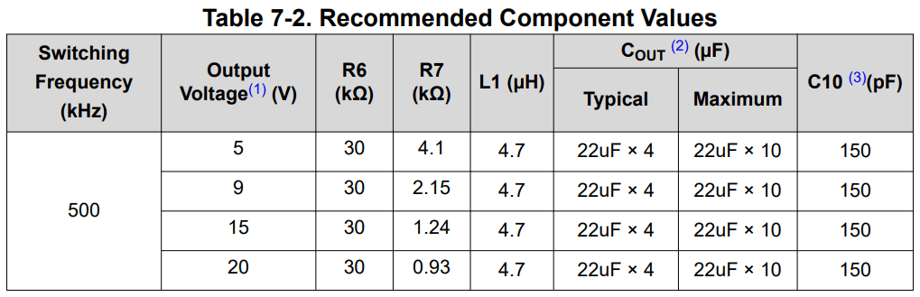
With the exception of the R7 value, I referenced this table for the component values in my schematic below.
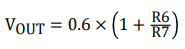
I used this formula provided in the datasheet to calculate R7 given a desired Vout of 24V and an R6 value of 30kohm.
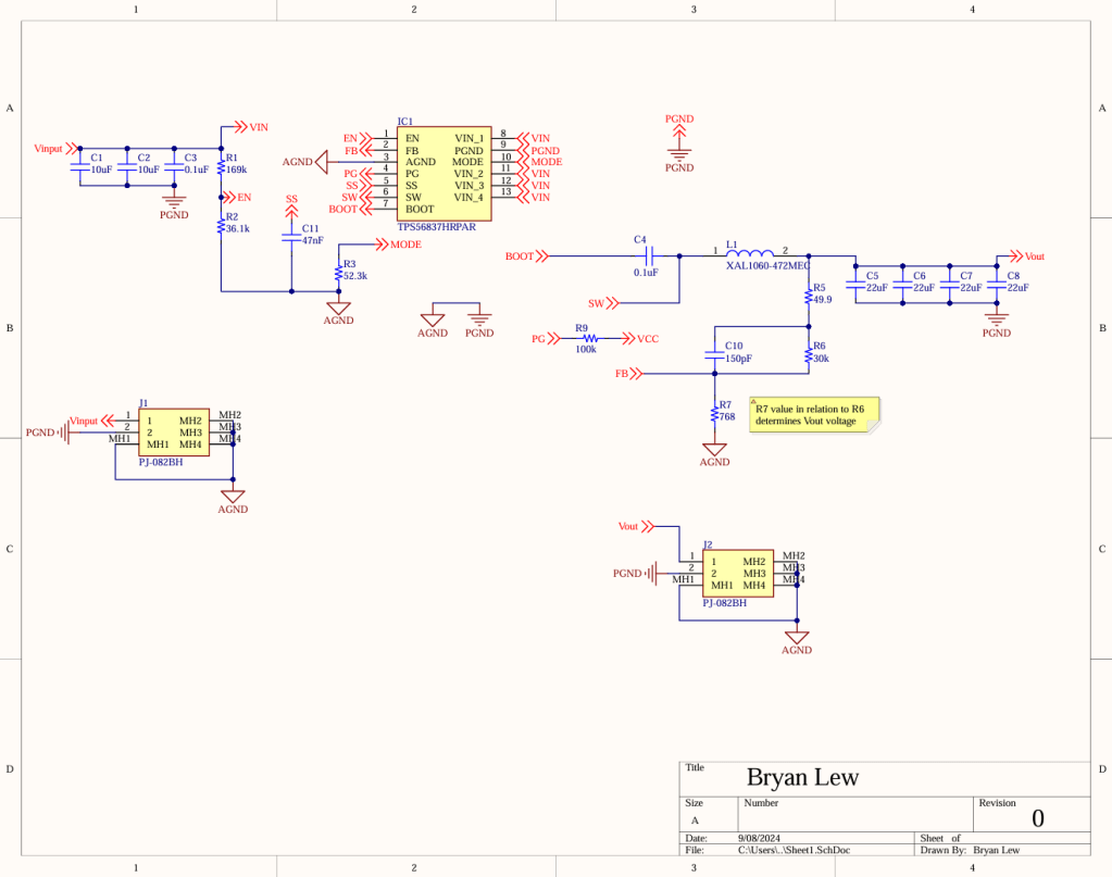
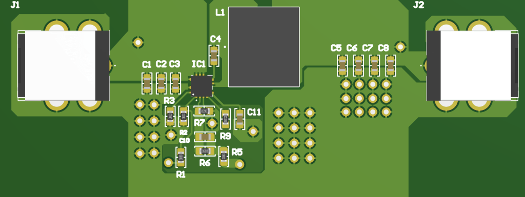
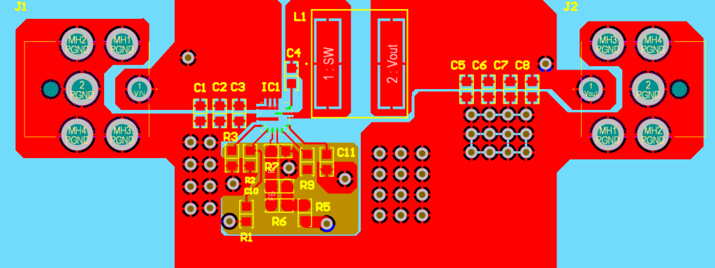
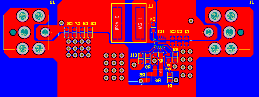
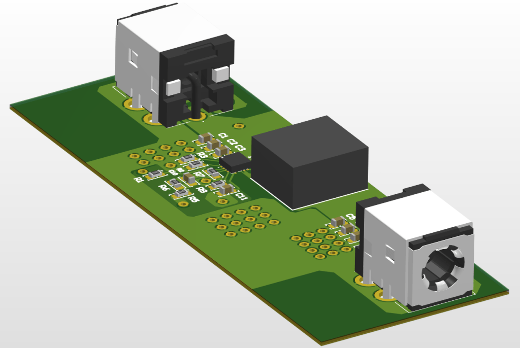
With the schematic completed, I moved onto the layout using a board size of approximately 7.5×3 cm.
After finishing the layout, I proceeded to prepare the board for manufacturing by generating the gerber files and BOM.
I ran my board through JLCPCB’s DFM check as seen above. I overlooked the clearance of vias to pads on accident but I went in and corrected most of the other issues highlighted by the DFM report. The silkscreen line width was disregarded.
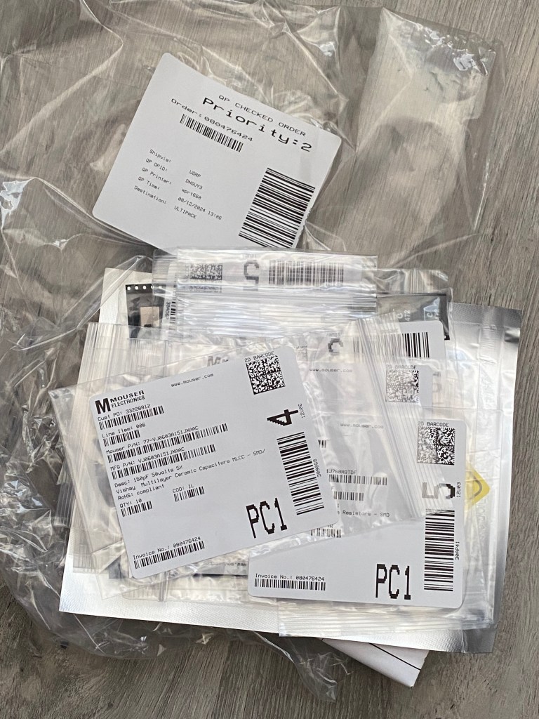
After ordering and receiving all of the parts for my BOM from Mouser, I went ahead and soldered everything on which took a few hours. I verified nothing obvious was shorting by using a multimeter to check the resistance of different traces, most importantly Vin and Vout with respect to GND.
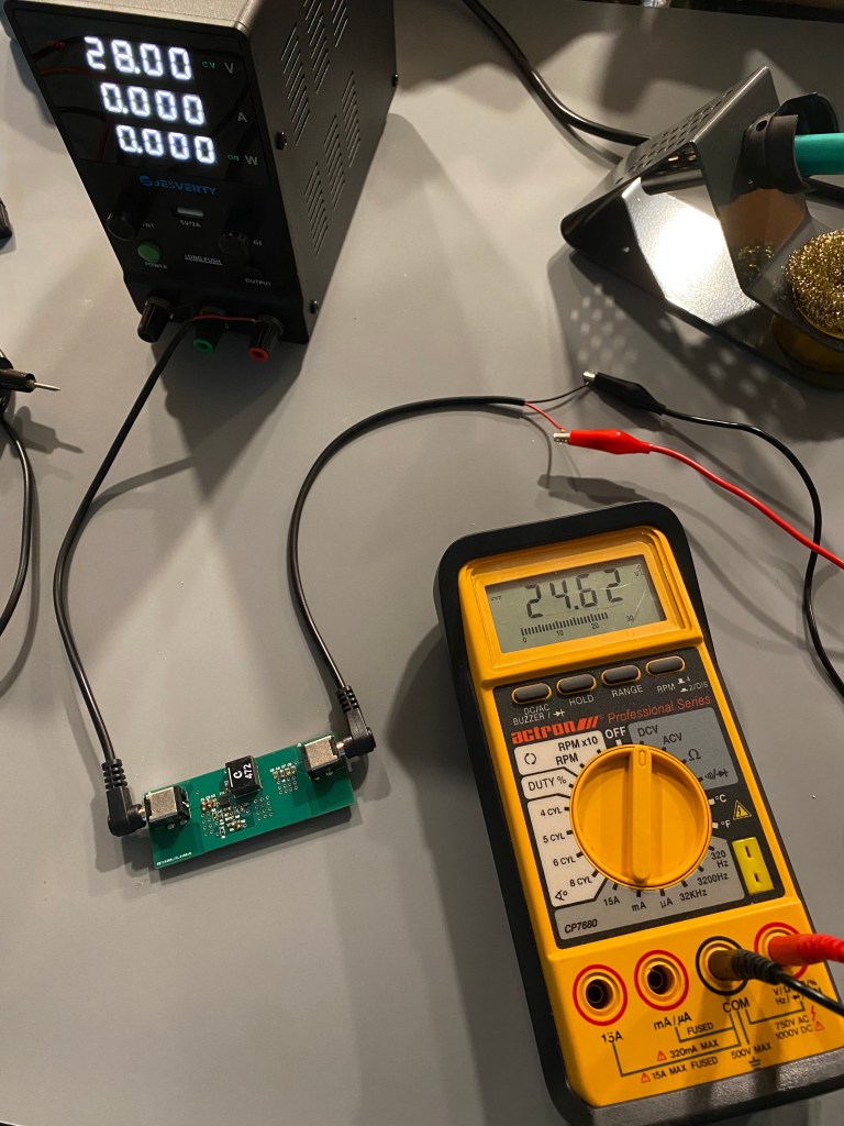
Then, I connected Vin to my power supply at 28V (the max input voltage of the Buck IC) and measured Vout. Fortunately, the output voltage was close to the expected 24V.

For fun, I decided to switch out R7 for a different resistor value to change Vout and I now got a reading of 1.2V.
After switching R7 back to its original value, all that was left to do was to try attaching an actual load to my board. I connected my soldering iron to Vout and brought it up to temperature. The board was able to power my soldering iron and melt some solder as demonstrated in the video (you can also see the power draw from the power supply).
Overall, I enjoyed working on this project and now I have a buck converter that I can utilize for some potential future projects.
